Function generator circuit built with LM324 chip
Below is the function generator circuit to be built using the LM324 op-amp chip.
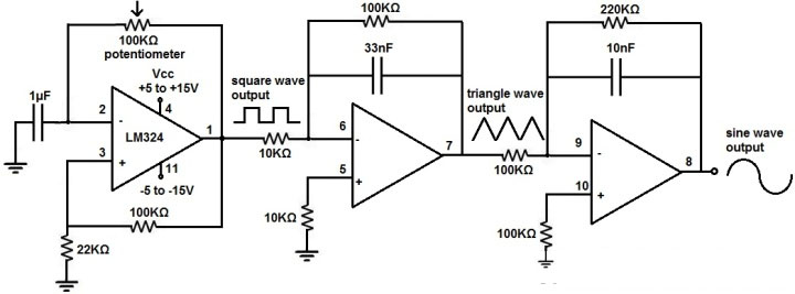
Figure4-Function generator circuit built with LM324 chip
The breadboard circuit for the above circuit is shown below:

Figure5- breadboard circuit for the above circuit
The above is the function generator chip built with LM324
Working Principle:
As mentioned above, the LM324 is powered by a DC voltage through pins 4 and 11. We feed anything from 5V to 15V to pin 4-VCC and anything from -5V to -15V to pin 11-GND, this builds up enough power for the circuit to run.
First Op-Amp: This op-amp generates a square wave. The 100KΩ potentiometer allows us to vary the frequency of the circuit. And it is a way to adjust the frequency of the output signal. So after the first op amp, we have a square wave. Next is the integrator circuit. When you feed a square wave into an integrator circuit, the output is a triangle wave.
After the second op-amp, we now have a triangle waveform as our second waveform. We then feed this triangle waveform into another integrator circuit. When you feed a triangle waveform into an integrator circuit, the output is a sine waveform.
After the third op-amp, we have a sine waveform, which is our third waveform. This circuit is very basic.
The first op-amp produces a square wave. We feed this square wave into an integrator circuit which outputs a triangle wave. We then feed this triangle wave into a second integrator circuit which outputs a sine wave.
The 100KΩ potentiometer allows a fairly wide frequency range, so the circuit provides good frequency adjustment, just like a standard function generator.
The circuit also allows easy amplitude adjustment. If you're using a DC power supply to power this circuit, all you have to do is adjust the voltage on the DC power supply to change the amplitude of the signal. If you're powering the circuit from batteries then you'll need to add the number of batteries needed to get the maximum voltage you need, then add a small value potentiometer, say 200Ω-500Ω, to allow voltage adjustment.
This is how a function generator circuit is built using an LM324 op-amp chip.
First Effort fail
https://www.calculator.net/resistor-calculator.html?bandnum=4&band1=brown&band2=black&band3=blue&multiplier=yellow&tolerance=gold&temperatureCoefficient=brown&type=c&x=Calculate
Second Effort
https://www.caspoc.com/help/handson/breadboard/signalgenerator/
Signal Generator
A function generator is a electronic device that can produce a variety of different waveforms. The one we will build can output square, triangle, and sine waveforms. Like standard function generators, the circuit allows for frequency adjustment by means of a potentiometer.
The circuit works on the principle of just using op amps. The LM324 is a quad op amp, meaning it's composed of 4 independent op amps. In this circuit, the first op amp produces a square wave. After that, the circuit uses 2 integrator circuits to convert the square wave into triangle and sine wave signals.
The function generator circuit we will build with an LM324 op amp chip is shown below.

This circuit is pretty basic. The first op amp produces a square wave. We feed this square wave into an integrator circuit, which outputs a triangle wave. We then feed this triangle wave into a second integrator circuit, which outputs a sine wave.
The first opamp produces a square waveform. The 100KΩ potentiometer allows us to vary the frequency to the circuit. And it's the way of adjusting the frequency of the output signal.
After the first op amp, we have a square waveform. What follows next is an integrator circuit. When you feed a square waveform into an integrator circuit, the output is a triangle waveform.
After the second op amp, we now have a triangle waveform, as our second waveform. We then feed this triangle waveform into another integrator circuit. When you feed a triangle waveform into an integrator circuit, the output is a sine waveform. However all depends heavily on the choice of the integrator constants made up by the R and C in the feedback of each opamp.

https://circuitdigest.com/calculators/capacitor-value-code-calculator
No comments:
Post a Comment